description of a developable hull design method with photos and comments on a series of real boats being built
Sunday, August 25, 2024
Boating is more Satisfying when the Boat is your own Design
Saturday, June 15, 2024
What is Next?
I sold two rowboats during the past week, helping to clear out the shop. I have one more that I want to sell. (Now sold to a gentleman in California; he drove here to get it.) If you have been following my blog, you can see that as I build a design, I am always asking "What could I do better?" Then the next build incorporates those changes. The boats I am letting go are perfectly adequate but have been replaced with slight improvements, sometimes with only aesthetic differences. And I am at a point where few new improvements come to mind on my rowboats. A sailboat would be a different project, but the Colorado mountains might not be a good place for consistent winds and sailing.
I have been looking for the proper trailer for transport. I finally located one, but it needs work (23 years old) and modification; it had been set up for hauling bicycles. I bought it; used boat-type trailers are hard to find in Colorado, especially light duty. I have replaced the tires, inner tubes, bearings, and axles. I exchanged its setup for bicycles with a 5 1/2' by 5 1/2' deck for small boats. Next project: I have discovered that not all the trailer lights work. The wiring is old (obviously) and not well protected.
I need to get out on a lake with my newest boats; that use may suggest further improvements. The boating season at the altitudes where we live, 7000+ feet, is only about six months long, making for a limited opportunity on our lakes.
This trailer came with a short tongue and a long tongue. I attach the short tongue for use while in the shop. The trailer (a commercial build from California) has coil spring suspension and motorcycle-type tires. New tires are not easily found, but I was able to get two from Ebay.com.
Sunday, June 09, 2024
Careers and a Hobby
My interest in boats, shared with my brother, started
when our uncle gave us a decrepit plywood pram.
It was poorly cared for and leaked.
We sealed the seams with roofing tar and painted it with house
paint. Then we named it “Tar Baby” in
honor of the tarred seams. Later, our
family bought a boat for waterskiing, a sport we learned to love. Next, my brother and I each joined the US Navy Reserves
when we reached 17 y. o. and while still in high school.
My Navy service included crossing the Pacific Ocean twice
(LST hull, then destroyer), spending most of a year in the Mekong Delta, next providing coastal fire support, and finally cruising north from Vietnam to Japan for ship maintenance. My nautical education began with navigation
school in San Diego and subsequently continued with real life experience and
onboard texts as my guide.
USS Preston, DD-795, taken October 1966, a year before I was assigned to her. This was a WWII vintage vessel, capable of up to 35 knots (40 mph) but near the end of her service life. As well as serving as plane guard for the aircraft carriers in the gulf of Tonkin, its six 5-inch guns were used for coastal fire support. At 375 feet long, it would be considered small by today's standards.
One early morning, while on a training exercise off the coast of Mexico, I witnessed a rare event of the sun’s rays being bent,
diffracted, by the earth’s atmosphere just before sunrise so that, for a few
moments, I was able to see islands that were far beyond the visible horizon, more
than a hundred miles away. While
crossing the Pacific, we went through the edges of a typhoon, experiencing huge
waves crashing over the bow, waves sweeping across the deck, and the entire ship
shuttering as the plunging hull intermittently exposed the propulsion screws
from the seas. From instances like this, I developed respect for the unflagging nature
of the ocean’s power and its vastness.
After my release from the Navy, I went back to my mechanical
engineering studies at the University of California, Santa Barbara. The Pacific Ocean forms one boundary of the
campus. The school has a crew club (rowing),
surfing team, and a fleet of sailboats at Santa Barbara harbor. Taking a sailing class out of Santa Barbara,
I was intrigued by the forces in play determining sailboat performance. Joining crew club exposed me to the influences of wave versus frictional drag. At the same time, I needed a senior research
paper topic for my engineering studies.
Thus, I chose sailing hull design as the topic of my research paper.
I was able to design a system for tow testing scaled hull models
in a calm swimming pool with valid and consistent results. The drawback was that I needed to construct a
series of model hulls with varying parameters to test the influence of design changes
and be able to describe them mathematically.
Simple photos would not suffice.
Researching previous hull design information, sparse in the published
literature, I was able to customize mathematical equations and methods of
projection to describe a limited range of hull forms.
My research paper was successful with an "A" grade. But my search for fulfilling employment as an engineer was not so successful. Much of my duties consisted of reviewing architectural plans and financial data, looking for mistakes and ways to increase efficiency. Our engineering department was blamed for project cost overruns; in response, I did a comprehensive review of the past ten-years construction bids (for projects to be built several years later) showing that, in fact, it was the marketing department failing to allow for price inflation that resulted in the cost over-runs. The big boss was a marketing guy and did not want to accept my facts. I was disgusted and started looking for alternatives to these petty office politics.
Our Morgan 27 sailboat on San Francisco Bay. A very nice ocean-going boat, but the worst purchase decision I have ever made. Too many changes going on in our lives at that point to make such a commitment.I considered a degree in naval architecture, but, at a visit
to UC Berkeley, was told that ship design had no future in the US. Designing ventilation, plumbing, and
electrical systems for ships would be a better pursuit. I considered sailing around the world (even
to the extent of buying an ocean-going sailboat), but after reflection, realized
that was just escapism, avoiding difficult career choices. My degree would be obsolete by the time I
returned from such a voyage.
I considered medical school, but a suggestion from my wife, Dawn, changed my career path to dentistry, a whole new environment. My focus became people: biology, chemistry, physiology, and psychology. In our classes, little was said about the molecular structure of the materials we used, that was for engineers to know. Our dental text included a chapter with sections written by one of my UCSB engineering professors, but it was given little attention. Dawn encouraged me to apply for a military scholarship, not just for the financial help but also for the travel opportunities it provided.
Our first major assignment was in the country of Panama, near Colon, on the Atlantic coast. When friends there asked me to be navigator in bringing the trawler they had purchased from Miami to Panama, I had the chance to use my navigation training once again. I was very thankful that I had supplemented my Navy training with a text on Polynesian navigation, using nature instead of instruments, because their 'new' boat had little to offer for ocean navigation other than a compass and one chart. We arrived safely on schedule despite engine problems.
I really enjoyed my career in military dentistry, not completely retiring
until age 76 (including time as a military contractor). There were many patients I
could list where I was able to not just ensure healthy teeth but improve their
lives. That was always my goal. Let me give one example: a woman (wife of a soldier) came to our
office in the Netherlands in pain with her face swollen due to a tooth which had
rotted off into her jawbone (no visible tooth).
It was a surgical extraction with ample drainage of pus, but I was able
to treat her comfortably with adequate anesthesia.
After she departed, I told the receptionist, “I want to see the mouth
that kisses her mouth.” (her husband).
Because her husband was a member of the US military, I was able to
order him to come in for an examination.
Sure enough, he had significant dental problems also. Neglecting your dental health can be grounds
for separation from the military. We
treated both parents empathetically, comfortably, and were able to bring them
into healthy, confident smiles. Not just
treatment, but education and motivation.
Then, they voluntarily brought their children in, and we were able to correct
all developing problems. We replaced
fear, ignorance, neglect and shame with dental health and a confident future. What better professional reward could I have? This sequence was repeated with many other
patients. Being in the military, cost
(other than not wasting taxpayer money) was not a factor.
Can I tell one more story concerning the Army commander’s wife in Germany who was a dental phobic? I diagnosed a dental problem of hers before even seeing or talking to her (but I had treated her husband, the base commander, and he brought her previous radiographs to me). His wife was talking to my wife by telephone when she mentioned that she had a minor toothache. My wife whispered this comment to me. I told my wife to ask her if the discomfort was on the lower right toward the back of her mouth. She replied to my wife, "How can he know that!"
As a phobic, she had a past of visiting dentists only when forced by circumstances. She would then take home any records generated with her at the end of the visit. I had carefully reviewed all her previous radiographs (provided by her husband) before filing them and had noted a developing defect in that lower right area. After her toothache was comfortably treated, she came in for a series of cosmetic dentistry appointments, completely overcoming her phobia. How about another…. enough said. I could go on and on. Dentists tend to get little respect, but on multiple occasions I have witnessed the dramatic improvement in a person's entire outlook from a healthy, pleasing smile. That is all the satisfaction I need.
Designed and built here in Colorado for daytrips and waterskiing.
Was my engineering background to be forgotten? No. I
went back to my senior engineering research on hull design using mathematical
concepts. Over the years, I have built 14 boats using my mathematical design approach and expanding on it. While in dental school in Omaha, I built a canoe
for the small nearby lakes and rivers.
While in Panama, I built a cartoppable sailboat for the beaches, and shallow
reefs there. While in Alabama, I built a
twenty-foot, two-masted sharpie sailboat for the large reservoirs in that area. During a ten-year period (residency, Board
exams, clinic management) I was too busy for such projects. Part-time work and then retirement have given me more time and a
better workshop for my design ideas including two outboard runabouts.
I have enjoyed all of it: studying navigation, engineering,
dentistry, woodworking. My father, a high school graduate, taught
me by example that being a professional does not require a college degree; it
is your attitude toward the task at hand that makes you a professional.
Life
is a process of learning and becoming; dreams evolve to plans, then to
realization, while facing the challenges of new situations along the way.
We learn, grow, and find meaning as we explore the world around us.
Sunday, December 03, 2023
New project: a smaller kayak
Having just completed a large kayak with ample storage space, it weighed in at sixty pounds, which is too much for my wife. But the basic design looks good, now I plan to create a slightly smaller version of the same exact design. Frames will be spaced at 13.5" instead of 15" and the depth is reduced by 2.5". I wonder how different the hull will be visually. Progress will be slow because of the holidays, IRS tax prep, and a long-planned trip. Design dimensions are 153" by 26.6".
A hint of what is to come: The deck beams are laminated. They all have the same curvature; thus, they could all be built on the same form. The remaining parts of the frames are built from individual pieces that are half-lapped and then bonded together. The plank that all the frames are resting on will be the future keel. That keel will have a slight rocker by design. My strongback, such as it is, consists of a ten-foot long 2X6 resting on two sawhorses.
Paint and varnish added. I am using all Epifanes products and am pleased with the results. The seat is being varnished separately. Now I need to get a light trailer to carry either two kayaks or a single rowboat. Colorado has few lakes, and many are at altitude where they are covered by ice for almost half the year. Most marine products I use need to be ordered by mail. But the low humidity is excellent for boat building.
Saturday, July 22, 2023
Finishing the planked hull
Now that I have a fully planked hull to look at, I am asking myself, "Is this a kayak or a canoe? Dimensions are 27" by 170". I wanted to make a somewhat wide and stable hull for my wife, but I think it has more freeboard than needed, which gives it a canoe look. Whatever. I have already bought the keel plank for a next build.
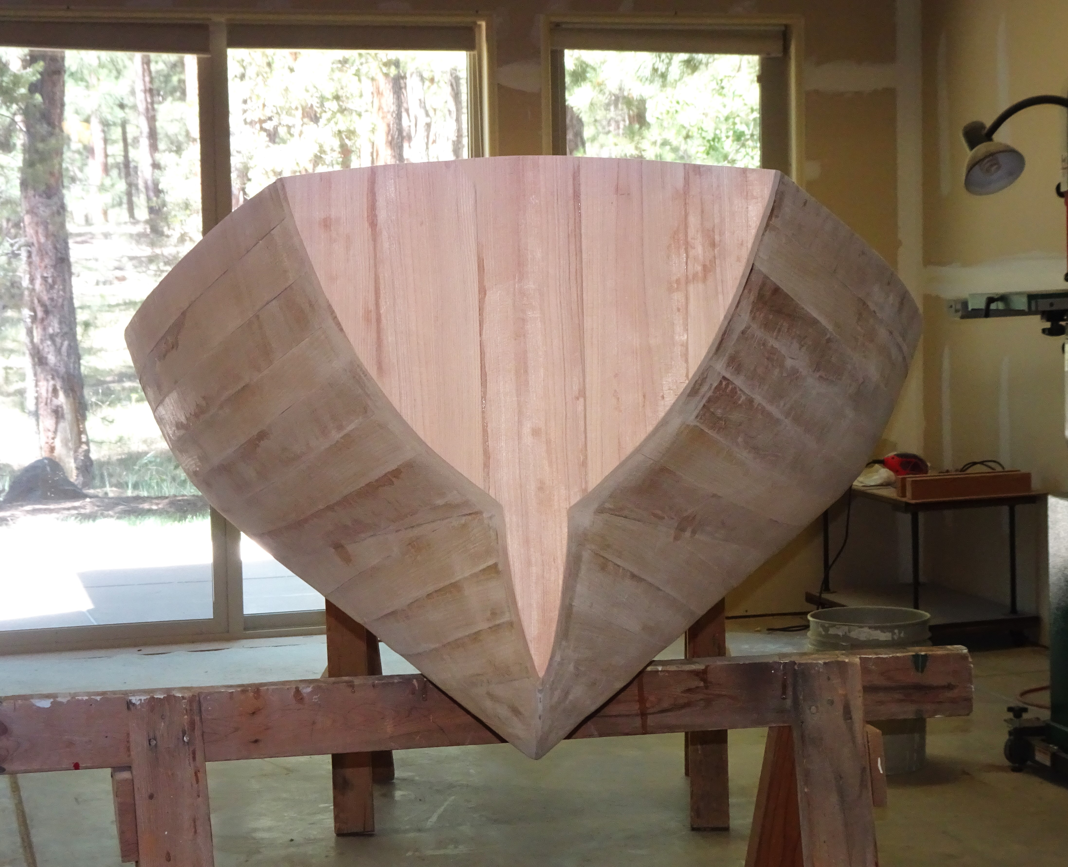
I will be turning the hull over for sanding, fill coating, and more sanding to get a smooth exterior. Looking at the hull, it would be very difficult to realize that this is a developable surface hull. Completely designed using the mathematical accuracy of developable projection; no strongback required, in the final step, instead of connecting all offsets on the hull frames with straight lines, they were connected using a smooth curve. By sheathing that curve with narrow planks (1.5" wide), the result is a curvaceous hull.
Next comes the sanding: Random orbital with 80 grit discs. My Porter-Cable sander is falling apart; time to replace it.My goal is not to sand it completely smooth. I want people to see that it is a wooden planked hull. What you see here are spots where squeezed-out resin was wiped off the hull surface.
Sunday, June 04, 2023
Rules for Creating Developable Hull Surfaces
Assume we are working in a mathematical X,Y,Z coordinate system where X define length, Y defines width, and Z defines height.
1. A straight line can be defined by two points in space or by one point and a constant slope.
2. A curved line can be defined by an algebraic equation(s) relating X, Y, and Z to each other.
3. Projections can be in the form of a plane, a cylinder, or a cone. The cylinder and cone do not need to be circular in cross-section and do not need to form completely closed surfaces.
4. A plane can be defined by holding one coordinate constant or by using a constant slope in space.
5. A cylinder can be defined by constant slope projections from an algebraically defined curve.
6. A cone is defined by projections from a single focal point to a defined curve or other series of selected points.
7. Projections can be combined by using common ruling lines (lines which are defined in both adjacent projections).
8. Surfaces can, thus, be built up by combining multiple projections.
9. Surfaces can be combined by common predefined border lines (straight or curved) or by intersections, either calculated or by graphic solution.
10. Locating a conic focal point close to a limiting curve or intersection will accentuate curvature in that localized area. Be sure that is that what you want.
11a. Cross section shapes (for frames) can be found by holding X constant and solving for Y and Z.
11b. Waterlines can be calculated by holding Z constant and solving for X and Y.
11c. Longitudinal sections can be calculated by holding Y constant and solving for X and Z.
12. Mathematical curves defining the relation between X to Y and X to Z can be separate equations.
13. Lengthwise, a defined curve can be made up of differing segments as long as they have a common slope at the point of juncture.
14. The easiest curve I have found to use is a parabolic or trajectory curve with coefficients chosen to create the length and curvature desired. The slope at any point is easy to determine. The length to any point along the curve can be calculated using a derived formula.
15. When creating a hull form, defining the midships cross-section shape and major chine is almost always the favored place to start.
The general form of equation I use is the following: Y=B(1-X^/L^) where "^" indicates the term squared. Y is half width, X is length measured from amidships forward, B is the maximum beam, and L is the overall half length.
The exact equation used for the forward width of my kayak is Y=8.1(1-X^/67.5^) where Y is calculated every 7.5 inches from X=67.5 to X=0 resulting in values of Y=8.1, 7.7, 7.2, 6.5, 5.6.... and so on. Note that the decreases are 0.1, 0.4, 0.9, 1.6, 2.5 and so on until Y=0 at the completion of nine segmental computations (9^=81). The slope at any point on the curve is (the change in Y multiplied by 2 then divided by the change in X).
Thus, the end slope of this curve is 2x8.1/67.5 or 0.24, this can also be expressed as a change of 0.9 inches in width for every 3.75 inches change in length. At the end of every attempted curve of a wooden board, there is always a short segment at the end where no fulcrum exists to exert torque to continue the curve to the very end and the end piece is straight (but angled).
I then add that short segment of straight line (wooden plank) to the end of my curve, resulting in an overall length of 71.25 inches and overall beam of 9.0 inches. The result is the equation and width offsets for the major chine.
At this point, you have either understood the concept or are totally confused; I will stop here.
Tuesday, January 31, 2023
Finalized kayak design. Work begins.
Calculating the length of a mathematically derived sheer curve. If I used a programmable calculator, I could do these calculations in one step, but I routinely use a simple TI-36X which I bought years ago. So, I need to do the calculations in a stepwise fashion. It is a calculation I only use once per boat design, not worth spending too many resources on.
This equation for curve length was derived by calculus integration of the mathematical curve equation. All my college engineering studies were not completely wasted.
Part of that can be done by the type of support provided beyond simply sawhorses. Additionally, I have completed calculations for the overall length of the sheer and its intersection with each frame. With a double-ended hull and each frame fixed at the keel plus port & starboard sheer locations, all frames can only assume one position. The entire frame will form a single "girder", at least in theory.
I have already drawn out the full-size patterns. Not hard to do when the largest frame is less than 30" wide and 15" high. The frames do not change when their spacing is altered.
The deck beams are laminated from thin 'cut-off' scraps I have been saving for a few years. I built a curved ladder to clamp the strips into a conforming curve.After the clamps have been removed. Starting to outline the cockpit. Next, I will flip it over and add a stringer at the major chine.
As I create a new design, I am always asking myself what could be done differently. When I look at this hull design (and after sitting in it), I feel like the deck should be 2.5" lower. There is more foot space present than needed. A lower deck would enhance paddling. Also, the hull could easily be 10% shorter. The changes would reduce weight and windage. I do not want to reduce stability; this is not meant to be an advanced paddlers design.
Tuesday, January 10, 2023
Starting a new design and build: Kayak
Last summer, my wife and I stayed at an island resort in Bocas del Toro, Panama, which furnished us kayaks to use in the island-strewn surrounding ocean. Since the region was a tropical bay, small waves were of local origin, wind-driven but not open ocean swells. Anyhow, we enjoyed the experience, and my wife said, "Can you build me a kayak?" Well, of course I can!
I built my first boat, a self-designed kayak, in 1975. Not a great design, but very appropriate for our circumstances at that time. Now I have the opportunity to do it again. My wife, Dawn, and I will never be hard core kayakers. What I have considered is something easy to store and transport, fairly stable, but also easy to paddle with a decent glide and directional stability.
Looking at the commercial roto-molded plastic kayaks, most are about 12 feet long and 2 1/2 feet wide. I used those dimensions as a starting point. My result, mathematically generated, will be about 12' 4" long and 28" wide with a waterline width of 23-24" depending on the load. Height at the midships sheer of 12" and at the cockpit center of about 14" (cambered deck). With a waterline width that narrow, stability must come from a centerline flat, gentle deadrise, and then progressive steeper topsides.
Concerning length, I have spaced the frames (or molds) 12" apart. A longer hull can be easily created by re-spacing the frames and redrawing the bow and stern entries. My 1975 kayak was almost 16 feet long, but it was for two persons.
Progress will be slow. We have other interests to deal with. (My wife wants to re-paint some of our home spaces.) Not a problem; we already have several boats. Actually, buying a light trailer is another task to research. I'll post some sketches soon.
This photo shows an overhead sketch view and profiles of some of the frames. There will be a one-inch rocker in the keel at both ends. I don't need exact drawings here because a table of accurate dimensions was the first thing created. Full-size frame patterns will be made from those dimensions.Wednesday, August 17, 2022
Now I have a boat to look at
Eventually, I will post a complete list of offsets/dimensions for my new skiff. Beyond the numbers, there are two details that I consider important to achieving a good result. 1) The listed longitudinal location of each frame is for the side closest to the center of the hull. The reason for this is that the center is the widest point. When fairing the hull frame, you preserve that dimension on the center-facing frame surface and taper the other side of the frame. 2) After plotting all the listed offsets for a frame, connect the dots using a fair batten or a French curve. Do not use straight lines if you want a nice smoothly curved hull surface. Then, when actually planking the hull, create a flat landing surface for each plank as it is adapted to the hull. This will provide stable adaptation with better bonding.
I used two-inch-wide planks because that is the thickest that my saw will cut and the widest that most of my clamps will span across. Two-inch planks are difficult (or impossible) to edge-set, but more surface is covered by each plank. Narrower planks will be easier to cut and easier to edge-set when needed. Thinner stock may also be easier to obtain. If using narrow, i.e., 3/4-inch planks, the curved frame edges may not need to be modified for plank landing (the curvatures are not significant over such a short distance)
Planking completed. The hull is 13 feet, 5 inches long. The beam when completed will be 46.5 inches. Ideally, I think a more usable length would be a foot longer. This is the shortest hull I have ever built. One reason I used the shorter length was a test for planking. A longer hull will have milder curvature and planks should adapt more easily.Before planking, a commenter called this a "flat-bottomed" boat. Only the 10.5-inch-wide keel is flat (and tapers at the ends).
.