Wednesday, May 13, 2009

The Design Becomes a Reality


I have already posted on the design of this boat, so I will skip that subject other than to mention that my initial "plan' consists of tables of computed offsets in an X,Y,Z three-dimensional framework. I am having computer issues with importing photos, so they will get posted a little later.

1. First job was to convert those dimensions into full-size patterns for all the frames and the curved keel forefoot. I used stiff rosin paper for the patterns, the largest pattern is about 36" by 68". The offsets only define the outline of each part; thus, each frame was then drawn as a series of boards with joining angles and gussets. A horizontal reference line was drawn at the same level for each frame; this was used to align them all vertically when mounted on the strongback. The centerline can be used to align them horizontally.

2. With full-size patterns it is relatively easy to build the actual frames, all 14 of them. An outboard engine is to be contained in a semi-well which intersects with three frames, so those internal details had to be included in the frame designs.

3. A strongback was built with vertical support posts attached at each frame position. The frames were sequentially clamped in place using a laser beam to align them. Then longitudinal components, starting with the keel, were bonded in place. I really was anxious to get the engine well fit and bonded in place. Being integrated with the deck, hull bottom, transom, and three frames and structurally important to transmit the power of the engine, its fit was critical.

Wednesday, December 24, 2008

Hull design using simple mathematics


The question of how to create more than just simple angular shapes from sheet materials caught my interest quite a few years ago when I built my first plywood-sheathed boat. To visualize the problem I was facing, I first used a flashlight to project the shadow of a wire of various curvatures and orientations onto a flat screen, a crude form of conic projection. Then I realized that if I could model the curved wire mathematically, the same thing could be done in abstract space with highly accurate results. From this, I developed an approach that has worked well for me and, to my knowledge, hasn’t been described elsewhere. I hope to describe it here to learn whether anyone else is using a similar approach or if anyone might benefit from it.  Instead of attempting a comprehensive description (which would put everyone to sleep), I’ll go through a sample design (for the boat I am now using) which illustrates the approach while ignoring details.

 The technique does not require a drafting board or a computer. An inexpensive pocket calculator is the minimum equipment needed. The approach relies on two simple concepts: First, a chine description is created from which you can pick off many closely-spaced exact offsets. I use mathematical relationships to do this (think trajectory or parabolic curve), but any method which results in multiple well-distributed exact offsets is adequate. Second, for any line in a three-dimensional x-y-z coordinate system, as we move along such a line the changes in x, y, and z are proportional to each other according to the slope. 

Thus, if we know the change in one coordinate, we can calculate the change in the other two coordinates. By calculating the new coordinates of many exact points when projected into a different plane, we can derive the offsets for as many transverse sections as desired, create another chine, describe the entire length of the keel, and establish the sheer. A table of accurate offsets is the first result; then the hull sections can be drawn or sketched on graph paper to visually confirm what has been created. I use X to designate length starting at the forward end of the chine; Y designates width from the center line; and Z is the height above base, usually selected as the lowest point on the keel.

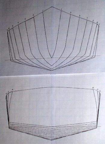
Bottom: With some idea of the desired length, beam, displacement and other characteristics of the proposed hull; the forward chine is created. For our example hull {see related drawing}, a few of the offsets starting at the bow are (0, 0, 20.25), (14, 6, 17.25), (28, 11.6, 14.45), (42, 16.4, 12.05), until we reach (119, 28.5, 6) at the point of maximum beam. A parabolic relationship is convenient to use, but other mathematical relations may be preferred depending on the purpose.  Integrate the equation and you can calculate the length of the curve or a section of it; differentiate the equation and you can calculate the slope at any point.

For this example, it was convenient to calculate offsets every 7 inches; that could be doubled to every 3.5” if necessary but commonly provides more data than needed. The point of maximum chine beam when projected to establish the keel coordinates becomes the lowest point on the keel. Several different types of projections could be used. I chose a parallel projection (constant slope) instead of a conic projection because, for this situation, the differences were small. The parallel projection is also easier to work with and minimizes severe localized curvature. I set the lowest point on the keel to be located at (63, 0, 0). The bow half angle, desired deadrise, and type of hull play a part in choosing this point.

Realizing that a unique line can be defined by a point and a slope, each offset on the chine gives us a point, and the slope to be used is the difference between the maximum beam at the chine (119, 28.5, 6) and lowest keel point (63, 0, 0); that difference is 56/28.5/6.0. We know Y=0 at the keel; thus, we can calculate the values of X and Z for each chine offset when projected to the keel or center line. A plot of these coordinates provides the keel shape {see area B1}. Similarly, we can find the offsets for all planned frames by using the established values of X for each frame (i.e. 14, 28, 42, etc.) and solving for Y and Z. Dividing the X:Y:Z slope by 4 reduces it to 14/7.125/1.5 which simplifies computations with changes coinciding with most frame intervals.

Having completed offsets for the forward portion of the bottom, the midsection is defined next {see area B2}. For a variable deadrise hull, a conic projection for the midsection helps reduce deadrise aft. This can be done by creating a short curve with the desired slopes at the keel; then creating a proportionally larger/longer parallel version of the same curve (in this case, twice as big) to extend the chine aft. Finding the apex of this cone is not necessary; it is enough to know that proportional parallel curves are part of a conic development. Continuing aft, the keel Z coordinate will increase more rapidly than for the chine because it achieves its end slope sooner; thus, the deadrise will diminish producing a flatter run. At the aft end of these curves the keel and chine have parallel slopes which are then extended by straight lines to the stern to produce a straight run of constant deadrise {see area B3}. For this hull, the deadrise is about 60 degrees at the bow, 20 degrees six feet aft, and 5.7 degrees at the stern.  For a constant deadrise hull this entire paragraph can be omitted; the keel and chine are simply extended aft as straight lines.

Topsides: Locating an apex for conic development of the hull side laterally in line with the bow half-angle results in a plumb bow profile. Moving the apex further laterally creates more flare to the bow section. By moving the apex moderately laterally the bow profile angle can be matched to the rise of the forefoot of the keel, avoiding a knuckle in the profile {see area S1}. Vertically the apex should be located high enough above the proposed sheer level to avoid any localized severe curvature to the sheer.  Longitudinally, the apex should be approximately halfway between the bow and midpoint, adjusted forward or aft depending on where you want maximum topsides flare. After trying out a few alternatives, I settled on locating the apex at (63, 40.5, 66).  Because any two points also can be used to define a unique line, using this apex and the series of chine offsets, many lines can be projected and their intersections with proposed frame locations in the anterior hull calculated.

Because a tumblehome stern was desired, a new apex for conic development was established closer to the sheer line once development from the previous apex reached the midsection. The new apex was connected by a common ruling line to the previous apex in a segment of slight curvature preventing transitional distortion of the hull surface in this area. Using the new apex, conic development was continued to the aft end of the chine curvature {see area S2}. This apex also provides one point, and the series of chine offsets provide second points so that many unique lines are defined. For each line, its intersections with every applicable frame location can be calculated to any desired exactness.

The initially established chine offsets, used to create the bottom, do not have to be used as the final chine position. In this case, aft chine is tapered through using a new curve to define the topsides. In creating a tumblehome stern, the aft chine, instead of being a straight line, is modified by a calculated curve bending toward the midline {see area S3}. As with the original chine, exact offsets are calculated every 7 inches, but this new curve extends in abstract space about six feet past the proposed stern. For projection from this new curve, the slope established by the last ruling line connecting the amidships apex with the aft end of the chine curve was used. Thus, this is a parallel projection. For the tumblehome stern, we are using one known point and a defined constant slope. Choice of projections depends on the desired result.

Deck: Because the deck curvatures were to be determined independently from the hull, several possible deck configurations could be constructed depending on the desired boat character and planned usage. After considering the alternatives, I elected to use a fairly simple cambered deck. A transverse deck curve of the desired camber and defined offsets (2.5“camber in a 40” long curve) was created. This curve was projected fore and aft mainly by parallel projection except for those areas where a planned open cockpit would allow slight longitudinal curvature to be incorporated without creating compound curvature. Y offsets were held constant while Z offsets changed slightly to reflect the fore and aft curvature.

The final determination of the sheer location is thus defined as the intersection of the deck surface with the hull topsides. Since both are fair surfaces, the sheer will also be fair.  Note that a cambered foredeck, if projected to the bow, will result in a slight "powderhorn" shape at its sheer intersection with the topsides.  If that shape is unacceptable, "powderhorn" curvature can be reduced by reducing foredeck camber or using a chosen Z coordinate profile for the sheer and departing from a true developable shape in the foredeck.  Because foredeck camber is comparatively minor, distortion will be minimal.

With the shape finalized, I made one final modification. I elected to change the X spacing from 7” increments to 6.75” increments. This shortened the overall hull length by 8.125” to about 18 ½ feet overall. No frame offsets were affected by this change; however, the anterior keel will need to be redrawn due to changed X dimensions.

Summary: At this point all that has been created is a boat-like shape. Many steps remain in creating a complete boat design. However, the only goal here was to demonstrate a method of mathematical projection to create desired developable shapes with more complexity than just a few simple curves. Developable hull surface design can be a logical sequential process focusing on one portion of the hull at a time. Using an initial set of exact offsets for a chine and some algebraic relations, a highly accurate set of offsets for an entire hull can be created. Conic, parallel and planar projections can be combined to create multiple contours in a single, fair developable surface. Modifications can be made, or alternative shapes considered, by changing mathematical coefficients and recalculating resulting values only for those parts affected. Accurate drafting skills and/or complex computer software are not essential.

Creating a form in abstract space removes physical restrictions on scale or degree of curvature. Routinely, dimensions are calculated to at least 0.01” accuracy, and many are exact. Curvatures are fair; no lofting to detect inaccuracies is required. Accurate dimensions are used to create drawings rather than the reverse sequence. A plan can be communicated using only sketches and a table of offsets/dimensions.

Saturday, July 28, 2007

Design evolution


Early runabouts were built on the warped-plane shaped, semi-planing hull bottom. This is the form that currently interests me most. I am not interested in the high horsepower, blasting through the water experience, but would rather glide smoothly, quietly, at moderate, breeze-creating speed and with good fuel efficiency. Achieving a smoothly transitioning warped plane hull bottom is also more interesting for me to design than a constant deadrise planing hull would be.


I built a series of three models in developing the current design. This design method does not use a drafting table or a computer program/screen to create the hull. The hull is shaped by the use of mathematical equations and geometric projections of calculated (x,y,z) coordinates until an entire table of dimensions to define all surfaces and/or intersections is created. The hull only becomes visible as the coordinates are plotted in a connect-the-dots fashion. Similarly, the entire boat is created by plotting the dimensions of each piece (coordinates of many points) to produce a pattern for each part, model or full size. Many dimensions are mathematically exact; the remainder are accurate within about 1/32". The "connect the dots" dimensions are closely spaced so that a short 2'-3' batten can be used when connecting them for a full-size pattern.


Mathematically almost any shape can be defined. In the real world each piece needs to be cut, bent or laminated to create the actual shape. Thus, I always try to design the final form using long, gentle curves rather than abrupt bends which are difficult to achieve during actual construction.

Monday, July 16, 2007

New direction

After I finished my model of a lobsterboat-style hull, I decided that, although fully functional, the boat looked drab and uninteresting. Rather slab-sided, not curvaceous enough, so I started over on the design. By changing co-efficients in some calculations, I gave the bow more flare, gave the stern more tumblehome, and flattened the run of the hull bottom. I also added a double cockpit and a fully cambered deck of classic runabout style. Then I started on building a new model. Drawings can't full visualize the three-dimensional form and proportions of such an object.

Lobsterboats are traditionally built in the range of 28 to 38 feet. Since I didn't want to exceed 20', the proper proportions weren't quite achievable on the reduced scale. Classic runabouts seem to be attractive to everybody, and I am no exception. I went to a wooden boat show and was disappointed in the selection of runabouts shown. Most were rather slab-sided, simple shapes; not a Riva among them. With the experience I have in creating developable shapes, I thought I could create something interesting.

I wanted fuel efficiency which generally means long and narrow. Twenty feet is the maximum length that will fit in most garages. The width had to be adequate for two people to sit abreast comfortably in the cockpit; that requires about a five foot width at the waterline. The result is a L/B ratio of 4:1 which is a reasonable compromise.

I am now finishing the 1/5 scale model of this new design and am extremely pleased with the result. This is the curvaceous and well proportioned shape I was hoping for. I hope to post pictures and more details in the near future. I don't plan to finish this model completely; I want to leave the deck open so that the structural details can be visualized- a guide for the future full sized hull. I do want to paint the outside of the hull and make it watertight so that I can check the hull buoyancy and loading.

Saturday, November 25, 2006

Model Lobster Boat


I am going to post these photos of the 4' model of my "lobster boat" even though I am not through painting it, because a cold front is moving in, and I want to get the boat in the water before the pond freezes over. Since this is a 1/5 scale model, I weighed the model; set it afloat; and added weight to bring it to its designed waterline. Indications are that the full size boat will be about 700 pounds and carry about a 1000 pound load at designed displacement.

Saturday, September 09, 2006

Updated drawings


I am working on a 4' model of my next boat using the calculated dimensions. In the mean time, I've used the frame patterns to create some approximate scale drawings of the full size boat. With a station spacing of 14", the bow half angle is 23.2 degrees. Bow height is 44". The deadrise at the stern is 6.2 degrees. Design draft is 8.4". The side view shows an enclosed bow from station 0 to 4, a small cabin from stations 4 to 7, an open cockpit with small coaming from station 7 to 14, and a planned stern well from station 14 to 16 for an outboard motor of about 15 hp.

Friday, May 19, 2006

Maiden Voyage


In Colorado, the boating that currently interests me is in the scenic mountain lakes. These are fairly large lakes with wooded shores and surrounding mountains. The wind is unpredictable, and the water is cold. I wanted something big enough that we could bring friends and picnic supplies for a day's outing; something quiet and leisurely to enjoy the scenery.

I had been thinking about a semi-planning powerboat, but was not ready for the cost, extended time schedule, or building space needed to produce what I wanted. The Whitehall-type pulling boat seemed to be a decent option. The design steps weren't much different than a guideboat except for larger size and a transom. Picking the correct projections to get a proper wineglass shape was a new design exercise. A look at John Gardner's writings provided many hull details.

The final boat was 18' 4" by 4' 9" with two sets of oarlocks and a small transom where an electric trolling motor could be mounted. The deadrise midships is 16 degrees. Today we were finally able to take it out for the first time, and everything went well. There are some adjustments to be made, mainly on the trailer and custom cradle used to transport it. I haven't made custom oars for it yet. The ones I have are too short, but okay if the trolling motor does most of the work.

Wednesday, May 10, 2006

A 20' semiplaning powerboat


I have completed the lines drawing (okay, not really the drawing, but all the mathematical measurements/offsets) for a 5 1/2' by 20' semiplaning powerboat hull. It will have lines similar in many ways to a scaled-down lobster boat. At 20 feet and trailable, I plan to use a bimini top instead of a fixed cover over the steering station. It will probably not get built until we move into a new house with a larger shop (current home is on the market). I do expect to build a 4' model in the near future.

Tuesday, May 09, 2006

Guideboat pictures


Apparently, my last post was too long to include the planned photos; so here they are.

Monday, May 08, 2006

Adirondack Guideboat Concept

Up to now I had used a mathematical approach to boat design to make boats which were relatively quick and easy to build. Now I decided to use the same technique to produce designs with more complex and interesting curvatures. We were living in the Thousand Island area of northern New York, and I had read some articles about the Adirondack guideboat. I visited the museums at Blue Mountain Lake and Clayton, also the Canadian National Canoe Museum. I studied the curvatures of the hull forms, trying to picture the underlying curves and implied ruling lines. Most planked hulls can be thought of as many developable surfaces, each the width of a plank, whose intersections form many chines. By incorporating multiple chines and multiple projections, many hull forms can be closely approximated. The guideboat appeared to be one of those designs.

 My final design has a 7" wide plank keel and a 1/3 deadrise slope amidships. This facilitated a low seating position and a low center of gravity. Using a double chine, the hull flared from about 28-30" at the waterline to 42" at the sheer to provide a decent width between oarlocks. Length was limited to 14 1/2', since that was the amount of space between the water heater and furnace in our home's basement building location. I reduced the upward sweep of the sheer in the ends. I know such a sheer looks pretty and may simplify planking, but it is also extra windage on the hull.

Each hull panel was formed from three projections. Each panel end had a conic projection with another amidships to link the other two. I use just a pocket calculator to do the math and freehand drawings (on engineering graph paper) to visualize the results. Because of the complexity of the hull panels with multiple projections, the hull shape is defined by the boat's skeleton, and the panel shape determined using patterns. Dimensional accuracy is within 1/32". Conic projection tends to produce changing bevels at each frame; thus, I used a plane to set the bevels after the frames were placed on a strongback. Knowing the exact direction of projection and using a straight edge, that is not difficult.

Actual construction was done almost entirely with hand tools in our cramped little basement. When designing, I visualize projections in three types. The parallel projection is the simplest; the direction of projection is contained within a plane formed by two axes in an x,y,z coordinate system and can be defined by a simple slope. It is characterized by identical panel slopes at each station from bow to stern. What I think of as a cylindrical projection cut across all three axes in a coordinate system and can be defined as a ratio, x:y:z. The "cylinder" is not round but instead the shape of the underlying trajectory or other curve. This projection has many of the advantages of the conic projection but is easier to use.

With the conic projection all lines emanate from an apex defined by a set of coordinates (x,y,z). If the apex is positioned too close to the surface being defined, an adjacent area of extreme surface curvature may result. If the apex is positioned too far from the surface being defined, the result has little or no advantage over a cylindrical projection. For me, the conic projection is best used where accentuated local curvature is desired or to link together other projections through converging ruling lines.

This little green faux guideboat performs great. It is light, dry, buoyant, maneuverable, and fast. I do think it would be faster if it were 1-2' longer. The two seats are removable and when positioned fit snugly around the frames. With one person, the rower's seat and attached footrest is placed in the center of the boat. For two people, the rower's seat is placed on the other side of the oarlocks and the second seat is placed at the other end to maintain balance.

Sunday, May 07, 2006

A real disappointment

We were living in Virginia and had a 60-acre lake just 1 1/2 blocks from our home. I was very busy at my job, but the temptation was there. It had been almost ten years since I built my last boat. Why do we build boats anyway? For me it is the creativity, making reality from just a vision in my mind. In this case my vision was cloudy. I was thinking, row, paddle, motor, maybe sail. A boat designed to do many things will do nothing well, and that's what happened.

The boat was about 3 1/2' by 15', had a double chine and was designed with a parallel projection. This was a very quick boat to build (weeks). No frames. Instead, I used a strongback and set up molds. All the panels were precut; tacked into place; seams epoxied; and a layer of glass laid down. Then popped it off the molds, and the inside was glassed. The weight of all that glass and resin made it heavy to cartop. The big error was that I added a transom, in case I wanted to motor, then added enough rocker to keep the transom out of the water. On a small, round-bottomed boat that takes quite a bit of rocker. Consequently, the boat tracked poorly.

The final insult was that the movers smashed the boat, punching a hole in the bottom, splintering the thwarts and delaminating the plies in the plywood with a smash to the bow. It now serves as a sandbox. And there are no photos I can find.

Panama Skiff


We arrived in Panama just in time (1979) that I could buy a few sheets of marine 1/4' plywood before the Panama Canal Company went out of business. No trailers or launch ramps available; shallow coral reefs off all the beaches, but beautiful deserted coves to visit with (by now) an entire family. Thus, I designed a little yellow skiff, 4' (40" waterline beam) by 15 1/2 ', with a daggerboard, rudder and sprit sail. I was able to get Sailrite sail cloth and WEST epoxy through the mail. Again, I calculated the length of the chine, sheer, and sheathing panels and all offsets so that the parts went together smoothly without having to use a strongback. The only drawings I used were just sketches for visualization. I had estimated the hull rocker correctly in design, so the boat performed nicely. We went picnicking, snorkeling, fishing and just exploring. It was light enough that we could cartop the boat on our Toyota wagon to bays along the Atlantic coast.  This boat was a great success.  I sold it when we left Panama.

We sailed it on Lake Gatun and in the ocean.  Once, when sailing on Lake Gatun by myself, a gust of wind broke the mast, and I had to row for a mile or more to get to the nearest landing.  Another time my wife suggested that we sail our little yellow skiff down the coast to a new beach.  Once we got out in the open ocean, I decided that this boat was not built for stresses imparted by such large waves, and we turned back, but the boat did not fail us.    

Kayoe or Canak?


I designed and built my first boat in the mid 70's, when we were living in Nebraska. I was a busy student with limited budget and time. The area has small lakes and shallow rivers and creeks but plenty of wind sweeping in off the plains. Consequently, I designed a sort of cross between a canoe and kayak. Double chine, plank keel, low freeboard, partially decked, approx. 16' by 3'. Also, it had to fit out the kitchen window after hauling it up the basement stairs. Using trajectory curve mathematics (and a slide rule!), I was able to compute the length of both chines, the sheer, and sheathing panel lengths as well as calculating all offsets.

No strongback was needed; all parts fit together as cut. A friend had recently built a Windmill sailboat. He was impressed as I simply put the pieces together. I had used a parallel projection, so all bevels were constant angles which were easy to precut. Thus, I was able to get tight joints and use resorcinol glue successfully. As an experiment, I built a pair of leeboards, attached a push-pole rudder, and used a wooden closet pole for a mast and nylon tarp for a sprit sail rig. With this I was able to maneuver up and down the lake but sailing rigs don't get much cruder than this.

Thursday, May 04, 2006

Where did this unusual interest originate?

Far back in college (1970), I took a sailing course which interested me, all sorts of subtle influencing factors in sailboat behavior. I was studying engineering and needed an idea for a senior research project. So, I decided to study sailing hull design. For research, I devised a simple hull towing routine: tow hulls with a range of measured forces and record resulting achieved speeds; vary the hull design and evaluate the change in performance.

The next question became, how to exactly describe a hull's shape and how to alter only a single or limited number of variables in the hull so as to independently test the influence of each variable in resulting performance? You can't just say that this hull looks this way, and the next hull looks like that. You must be able to describe the hull shape mathematically in exact terms. I found some equations in the Proceedings of the US Naval Institute, but they were far too complicated for my simple project. I found the trajectory curve in physics textbooks, a parabolic equation form, had the right characteristics. Such a curve has the appearance of a boat waterline; it can be integrated to find its length; it can be differentiated to find the slope at any point.

 The trajectory curve (also called parabolic) is easy to work with. It describes the motion of an object displaced at some angle from its rest position by an external force which then is brought back to its rest position by gravitational forces. Not exactly the Navier-Stokes equation of general fluid mechanics, but at least it is analogous to the motion of a water molecule displaced by a passing hull form. The research project was successful but very limited in extent due to the complexity of the many variables and the need to build a new model for each design change.

Fast forward a few years: I changed careers forever, leaving engineering for the new profession of dentistry. I didn't dislike engineering intellectually; I just didn't like the environment, being viewed as just a technical nerd, a contract-following migrant laborer. But I didn't want all my engineering knowledge to atrophy.  I chose to review my senior research subject and, as a spare-time evening hobby, started playing with the mathematical hull design concepts to create hull forms of interest. Mathematical techniques match very well with the concept of conic projections to produce entire surfaces. Conic projections match very well with the use of plywood hull sheathing which speeds actual construction time. You have to actually build a boat occasionally to prove that your ideas really work (and that you are not completely crazy).

Over the next forty-plus years I have mentally designed a number of hulls for various purposes, and I ended up building thirteen of them. My family and I have lived in many places. Each hull was designed for a particular set of circumstances and an envisioned purpose. I've learned something from each boat. If I were to revisit any design, I could find improvements to make, but that just makes it interesting. In subsequent entries I hope to post photos of some of the boats I have built and the lessons I learned from them.