Up to now I had used a mathematical approach to boat design to make boats which were relatively quick and easy to build. Now I decided to use the same technique to produce designs with more complex and interesting curvatures. We were living in the Thousand Island area of northern New York, and I had read some articles about the Adirondack guideboat. I visited the museums at Blue Mountain Lake and Clayton, also the Canadian National Canoe Museum. I studied the curvatures of the hull forms, trying to picture the underlying curves and implied ruling lines. Most planked hulls can be thought of as many developable surfaces, each the width of a plank, whose intersections form many chines. By incorporating multiple chines and multiple projections, many hull forms can be closely approximated. The guideboat appeared to be one of those designs.
My final design has a 7" wide plank keel and a 1/3 deadrise slope amidships. This facilitated a low seating position and a low center of gravity. Using a double chine, the hull flared from about 28-30" at the waterline to 42" at the sheer to provide a decent width between oarlocks. Length was limited to 14 1/2', since that was the amount of space between the water heater and furnace in our home's basement building location. I reduced the upward sweep of the sheer in the ends. I know such a sheer looks pretty and may simplify planking, but it is also extra windage on the hull.
Each hull panel was formed from three projections. Each panel end had a conic projection with another amidships to link the other two. I use just a pocket calculator to do the math and freehand drawings (on engineering graph paper) to visualize the results. Because of the complexity of the hull panels with multiple projections, the hull shape is defined by the boat's skeleton, and the panel shape determined using patterns. Dimensional accuracy is within 1/32". Conic projection tends to produce changing bevels at each frame; thus, I used a plane to set the bevels after the frames were placed on a strongback. Knowing the exact direction of projection and using a straight edge, that is not difficult.
Actual construction was done almost entirely with hand tools in our cramped little basement.
When designing, I visualize projections in three types. The parallel projection is the simplest; the direction of projection is contained within a plane formed by two axes in an x,y,z coordinate system and can be defined by a simple slope. It is characterized by identical panel slopes at each station from bow to stern. What I think of as a cylindrical projection cut across all three axes in a coordinate system and can be defined as a ratio, x:y:z. The "cylinder" is not round but instead the shape of the underlying trajectory or other curve. This projection has many of the advantages of the conic projection but is easier to use.
With the conic projection all lines emanate from an apex defined by a set of coordinates (x,y,z). If the apex is positioned too close to the surface being defined, an adjacent area of extreme surface curvature may result. If the apex is positioned too far from the surface being defined, the result has little or no advantage over a cylindrical projection. For me, the conic projection is best used where accentuated local curvature is desired or to link together other projections through converging ruling lines.
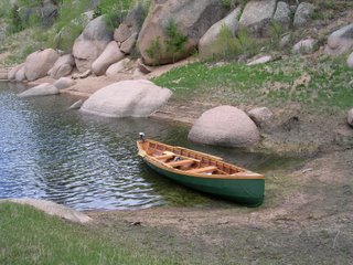
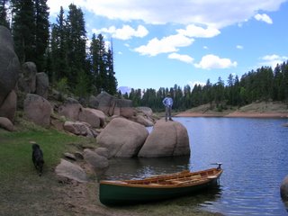
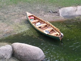
This little green faux guideboat performs great. It is light, dry, buoyant, maneuverable, and fast. I do think it would be faster if it were 1-2' longer. The two seats are removable and when positioned fit snugly around the frames. With one person, the rower's seat and attached footrest is placed in the center of the boat. For two people, the rower's seat is placed on the other side of the oarlocks and the second seat is placed at the other end to maintain balance.


