New project: a smaller kayak
Having just completed a large kayak with ample storage space, it weighed in at sixty pounds, which is too much for my wife. But the basic design looks good, now I plan to create a slightly smaller version of the same exact design. Frames will be spaced at 13.5" instead of 15" and the depth is reduced by 2.5". I wonder how different the hull will be visually. Progress will be slow because of the holidays, tax prep, and a long-planned trip. Design dimensions are 153" by 26.6".
A hint of what is to come: The deck beams are laminated. They all have the same curvature; thus, they could all be built on the same form. The remaining parts of the frames are built from individual pieces that are half-lapped and then bonded together. The plank that all the frames are resting on will be the future keel. That keel will have a slight rocker by design. My strongback, such as it is, consists of a ten-foot long 2X6 resting on two sawhorses.
Kayak frame completed. After I have the bottom and topsides planked, then I will alter the deck beams to create a cockpit.
1) The offsets for all frames were mathematically calculated. The shape of the plank keel and the bow entry & stern were also calculated. The total length of the sheer and length at each frame connection, also calculated mathematically.
2) Full size drawings of frames, bow & stern, and keel ends were drawn. Most data points are only a few inches apart.
3) Individual pieces were constructed from those drawings. Midlines were marked on each frame for visual reference during assembly.
4) Given that three points define a plane, each frame can only fit in one position defined by the keel and port & starboard sheer connections. At bow and stern, additional rigid triangles are created by the bow, keel, and port & starboard sheer connections at the adjacent frames. This forces the port & starboard sheers to meet in a predetermined fixed relation.
5) With epoxy and plenty of clamps, all connections only fit in one position, allowing assembly without use of a strongback form. Planking can now proceed on this rigid underlying total frame.
Now I have started planking the hull. With natural wood, each plank has to be considered individually. Few are absolutely straight. None are the 14+ feet long needed; thus, each requires a scarf joint. I ran them all through a planer to get uniform thickness. The initial planks all are positioned in the 1st projection of the hull form, meaning they all lie in one plane and can be laid straight without any taper.
But this is a triple chine hull (four projections); at the turn of the bilge, angles change several times, and intersection of planes required that planks located at the turn of the bilge be tapered and less than full length. The taper was determined by clamping the future plank in place and then tracing the overlap from the inside of the hull as a guide for trimming.
No fasteners used; tomorrow I will bond this partial length plank in place with epoxy and plenty of clamps. Instead of spiling, I clamped the proposed new 1.5" wide plank in place and then traced (inside the hull) with a pencil the overlap between the new plank and previous plank. This guidance was then used to trim the new plank to its tapered form.
No strongback or forms used. The plank keel, frames, and stems create a solid skeleton to build on.
Planking of the hull is complete except for finishing. Next, I will concentrate on cleaning up the interior and finishing it. Other tasks to consider are the sanding and filling of the hull exterior and planning the cockpit and decking. Still, this is a nice milestone of completion where it really looks like a boat.
Three coats of varnish on the interior. The exterior has been sand/fill/sand with a flowable epoxy paste. Now I am creating a contrasting pattern of decking planks. The color difference will be enhanced when I start varnishing. The darker planks are select alder wood. Alder is normally known for its knots; this is select alder; no knots, but still there are variations in the grain structure which cause slight curves in these planks. In a ten-foot plank, you may find 2-3 slight curves.
When you are laying multiple adjacent planks, you can't allow gaps due to this waviness. Thus, each plank needs to be fitted to its position, slowing the process.
Finishing the planked hull
Now that I have a fully planked hull to look at, I am asking myself, "Is this a kayak or a canoe? Dimensions are 27" by 170". I wanted to make a somewhat wide and stable hull for my wife, but I think it has more freeboard than needed, which gives it a canoe look. Whatever. I have already bought the keel plank for a next build.
I will be turning the hull over for sanding, fill coating, and more sanding to get a smooth exterior. Looking at the hull, it would be very difficult to realize that this is a developable surface hull. Completely designed using the mathematical accuracy of developable projection; no strongback required, in the final step, instead of connecting all offsets on the hull frames with straight lines, they were connected using a smooth curve. By sheathing that curve with narrow planks (1.5" wide), the result is a curvaceous hull.
Next comes the sanding: Random orbital with 80 grit discs. My Porter-Cable sander is falling apart; time to replace it.
My goal is not to sand it completely smooth. I want people to see that it is a wooden planked hull. What you see here are spots where squeezed-out resin was wiped off the hull surface.
When planking the hull, I put a bead of epoxy paste on the edge of each preceding plank before adding the next plank. That requires cleanup of the squeezed-out resin, but better that than a dry joint. When planking was complete, I used a disposable brush and un-thickened resin to fill any remaining small voids. I then used a flowable resin mixture, thickened with WEST 407 fairing filler, and wiped the entire hull using a flexible plastic squeegee.
That was followed by progressive sanding: 60 grit, 80 grit, and 120 grit (by hand). This wasn't as onerous as it seems, using my new DeWalt random orbital sander. Repeated vacuuming and next I will wipe down the hull surface before putting on a coat of primer.
Changed my mind. I was anxious to take on the deck sheathing. First, I cleaned up resin blebs in the interior and put down three coats of Cetol plus a high gloss sealer coat on the interior. Now, I am applying deck planks two at a time, port and starboard working toward the centerline. I will be adding hull access ports fore and aft as the planking proceeds.
Then it will be time for a vacation break.
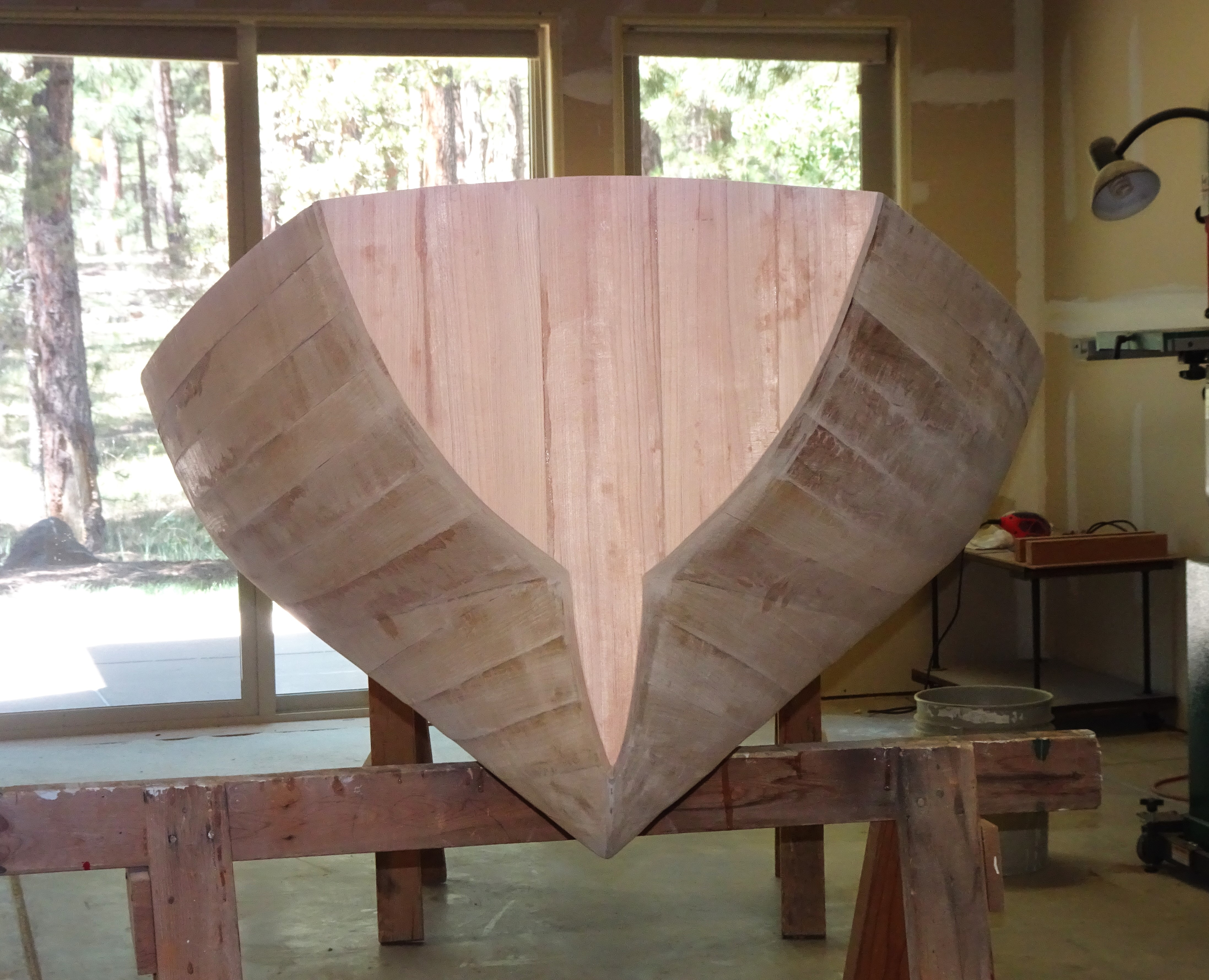
We are looking at the hull from the stern. The hull is not symmetrical fore and aft; the bow is actually slenderer than the stern. With the plumb ends, the waterline is almost 14 feet long. Next, I will create flush hatch covers for the fore and aft access openings. Then install a raised edge on the cockpit and build a seat for the paddler.
Those lifting handles are just resting in place; I need to do a lot of finishing on them. The deck has only had a rough sanding and will require further fill and smoothing.
Hatch covers and cockpit edging in place. This is a stern view; my camera makes it look like this would be the more pointed bow, but that is just wide-angle distortion. I love the flush hatches; am trying to decide what type of latching system to use without visual impairment.
Now, all I have to do is make a seat for the cockpit. Done! (but not shown)
Next up: Using the same design numbers, I am creating a smaller version of this hull: 10% shorter and 2.5 inches lower. Progress will be slow due to the holidays and a planned trip.
Rules for Creating Developable Hull Surfaces
Assume we are working in a mathematical X,Y,Z coordinate system where X define length, Y defines width, and Z defines height.
1. A straight line can be defined by two points in space or by one point and a constant slope.
2. A curved line can be defined by an algebraic equation(s) relating X, Y, and Z to each other.
3. Projections can be in the form of a plane, a cylinder, or a cone. The cylinder and cone do not need to be circular in cross-section and do not need to form completely closed surfaces.
4. A plane can be defined by holding one coordinate constant or by using a constant slope in space.
5. A cylinder can be defined by constant slope projections from an algebraically defined curve.
6. A cone is defined by projections from a single focal point to a defined curve or other series of selected points.
7. Projections can be combined by using common ruling lines (lines which are defined in both adjacent projections).
8. Surfaces can, thus, be built up by combining multiple projections.
9. Surfaces can be combined by common predefined border lines (straight or curved) or by intersections, either calculated or by graphic solution.
10. Locating a conic focal point close to a limiting curve or intersection will accentuate curvature in that localized area. Be sure that is that what you want.
11a. Cross section shapes (for frames) can be found by holding X constant and solving for Y and Z.
11b. Waterlines can be calculated by holding Z constant and solving for X and Y.
11c. Longitudinal sections can be calculated by holding Y constant and solving for X and Z.
12. Mathematical curves defining the relation between X to Y and X to Z can be separate equations.
13. Lengthwise, a defined curve can be made up of differing segments as long as they have a common slope at the point of juncture.
14. The easiest curve I have found to use is a parabolic or trajectory curve with coefficients chosen to create the length and curvature desired. The slope at any point is easy to determine. The length to any point along the curve can be calculated using a derived formula.
15. When creating a hull form, defining the midships cross-section shape and major chine is almost always the favored place to start.
The general form of equation I use is the following: Y=B(1-X^/L^) where "^" indicates the term squared. Y is half width, X is length measured from amidships forward, B is the maximum beam, and L is the overall length.
The exact equation used for the forward width of my kayak is Y=8.1(1-X^/67.5^) where Y is calculated every 7.5 inches from X=67.5 to X=0 resulting in values of Y=8.1, 7.7, 7.2, 6.5, 5.6.... and so on. Note that the decreases are 0.1, 0.4, 0.9, 1.6, 2.5 and so on until Y=0 at the completion of nine segmental computations (9^=81). The slope at any point on the curve is (the change in Y multiplied by 2 then divided by the change in X).
Thus, the end slope of this curve is 2x8.1/67.5 or 0.24, this can also be expressed as a change of 0.9 inches in width for every 3.75 inches change in length. At the end of every attempted curve of a wooden board, there is always a short segment at the end where no fulcrum exists to exert torque to continue the curve to the very end and the end piece is straight (but angled).
I then add that short segment of straight line (wooden plank) to the end of my curve, resulting in an overall length of 71.25 inches and overall beam of 9.0 inches. The result is the equation and width offsets for the major chine.
At this point, you have either figured the concept out or are totally confused; I will stop here.
Finalized kayak design. Work begins.
Calculating the length of a mathematically derived sheer curve. If I used a programmable calculator, I could do these calculations in one step, but I routinely use a simple TI-36X which I bought years ago. So, I need to do the calculations in a stepwise fashion. It is a calculation I only use once per boat design, not worth spending too many resources on.
This equation for curve length was derived by calculus integration of the mathematical curve equation. All my college engineering studies were not completely wasted.
I am completely committed to the 170" long by 27.5" wide kayak design. I have the keel plank roughed out and the bow and stern stem pieces also "roughed out". These pieces are only in approximate shape and will be trimmed and detailed more later. Next item will be a start on the ten frames. Incorporating one inch of rocker at the bow and stern created some complication. How will I ensure that the keel plank is held in the required position without using a building strongback?
Part of that can be done by the type of support provided beyond simply sawhorses. Additionally, I have completed calculations for the overall length of the sheer and its intersection with each frame. With a double-ended hull and each frame fixed at the keel plus port & starboard sheer locations, all frames can only assume one position. The entire frame will form a single "girder", at least in theory.
I have already drawn out the full-size patterns. Not hard to do when the largest frame is less than 30" wide and 15" high. The frames do not change when their spacing is altered.
The deck beams are laminated from thin 'cut-off' scraps I have been saving for a few years. I built a curved ladder to clamp the strips into a conforming curve.
Bow and stern pieces created from 2"X4" scraps. At this point they are only roughed out. I need to cut channels for the sheer and chine strips. I used a half thickness lap and Titebond III to join the two pieces.
All the frame pieces have been cut to shape. but that is only a beginning. I will be using a half lap when I start bonding the parts together. With sixty pieces to fit, it will be a lot of fine cutting.
The six parts for frame #5 (of ten) positioned on the full-size paper template. When more are ready, I will bond them with epoxy. Then they will be trimmed and notched for the longitudinal strips.
A preliminary look at how the frames line up on the plank keel. All pieces shown here are still unfinished, but it is motivational to see that the parts will fit together. The keel is presently 0.5" thick; I plan to plane that down to 0.4". I usually do that outside because it creates so much wood dust; however, we still have snow outside my shop door. I have other details to keep busy with for a while.
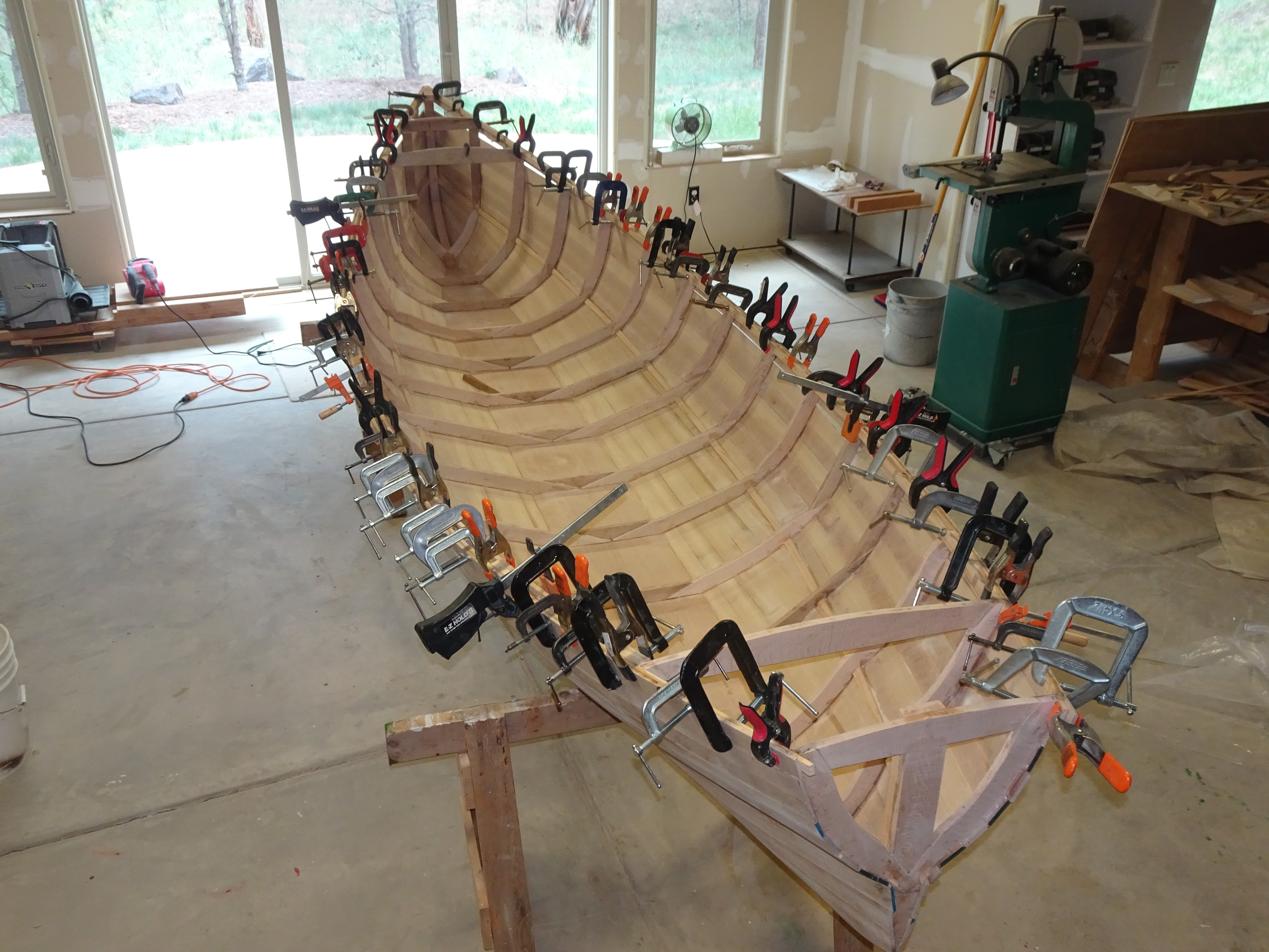
Finally, the ten frames, two stems, two sheer strakes, and keel are sufficiently complete that assembly can begin. I placed a straight 2X4 across two sawhorses and placed the keel centered atop that. Then I clamped the central section of the keel to the 2X4. Next, I placed a sawhorse under each end of the keel and added a few scrap wood pieces of the proper thickness to provide the desired rocker in the ends. Next, each frame was bonded and clamped in its proper place, spaced at 15" centers.
Port and starboard sheer strakes had been created, cut to proper length, and each intersection with a frame had been marked according to the calculated curved length of the curve. The calculation is amazingly accurate, hundredths of an inch, but my shop accuracy is only about 1/16". With both strakes joining at the stem ends of the double-ended hull, there is less chance of distortion. Unfortunately, after removing all the clamps, I see that frames #3 & 8 are about 1/4" out of alignment at sheer height.
With each frame fixed in place by the keel and port & starboard strakes (3 points define a plane), it was only a matter of having sufficient clamps to maintain that position until the epoxy hardened. No fasteners have been required thus far. This provides the basic framework for the entire hull. I will add another strake at the turn of the bilge and outline the cockpit; then it will be time to start planking.
The only strongback needed has been a straight 2X4 (6-8 feet long) and some sawhorses. Accurate measurements along the curved sheer strake made the difference.
I have plenty of clamps of all sorts.
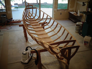
After the clamps have been removed. Starting to outline the cockpit. Next, I will flip it over and add a stringer at the major chine.
Kayak frame with more details added. A cardboard pattern is clamped on the lower right. That area is developable, thus, could be sheathed with a single plywood sheet, but that is not the alternative I have chosen. This pattern simply gives me a better idea of how the planking should be laid out.
Stringer added. Then it is time to fair all the frames and the stems, then create a shelf on the plank keel edge to support the garboard. I use an angle grinder for fairing; the stems take some serious wood removal to get the proper taper. For the edge of the plank keel, I use a router. This time I used a full-size router, its weight made it easier to control; not as easily deflected by variations in the wood grain. Near the ends of the keel, you are changing the angle and following a curve; thus, you need freehand control without a guide.
The intersection of the plank keel and the stem. The edge of the plank keel has been routed to support an edge of the garboard plank, and the stem has been beveled to support the plank ends.
I have purchased some planks of knotty alder for the sheathing. Why knotty alder? 1) It was cheap. 2) It was high quality; it looked somewhat like select alder. 3) After I rip it into 1/4" planks, I can scarf out any significant defects and knots. But we are taking a break before I get started on that next step.
Two months later and the break is over. I have ripped the knotty alder into 0.2" thick planks, cut out the significant knots and other defects, and then scarfed the resulting pieces into 15 (so far) 15-foot-long planks. With planks only 1.5" wide and my chop saw set at a 7-degree angle, it was easy to get consistent, smoothly beveled scarfs. The knots were frequent enough that most of my 15-foot planks have multiple scarfs.
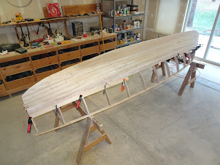
Progress. Planked up to the major chine. These planks have been straight and full length. The next planks will be more complicated, either tapered or curved.
As I create a new design, I am always asking myself what could be done differently. When I look at this hull design (and after sitting in it), I feel like the deck should be 2.5" lower. There is more foot space present than needed. A lower deck would enhance paddling. Also, the hull could easily be 10% shorter. The changes would reduce weight and windage. I do not want to reduce stability; this is not meant to be an advanced paddlers design.
The present hull will permit more stowage and allow a more relaxed seating position. Every tradeoff is a compromise.
Getting close to completing sheathing the hull. Then I will turn it over, lightly sand, then go over the hull with a flowable epoxy paste to fill seams and provide a smooth surface. I'll let that cure while doing some finishing to the interior. Then I will do final sanding on the exterior and start on the deck.
Starting a new design and build: Kayak
Last summer, my wife and I stayed at an island resort in Bocas del Toro, Panama, which furnished us kayaks to use in the island-strewn surrounding ocean. Since the region was a tropical bay, small waves were of local origin, wind-driven but not open ocean swells. Anyhow, we enjoyed the experience, and my wife said, "Can you build me a kayak?" Well, of course I can!
I built my first boat, a self-designed kayak, in 1975. Not a great design, but very appropriate for our circumstances at that time. Now I have the opportunity to do it again. My wife, Dawn, and I will never be hard core kayakers. What I have considered is something easy to store and transport, fairly stable, but also easy to paddle with a decent glide and directional stability.
Looking at the commercial roto-molded plastic kayaks, most are about 12 feet long and 2 1/2 feet wide. I used those dimensions as a starting point. My result, mathematically generated, will be about 12' 4" long and 28" wide with a waterline width of 23-24" depending on the load. Height at the midships sheer of 12" and at the cockpit center of about 14" (cambered deck). With a waterline width that narrow, stability must come from a centerline flat, gentle deadrise, and then progressive steeper topsides.
Concerning length, I have spaced the frames (or molds) 12" apart. A longer hull can be easily created by re-spacing the frames and redrawing the bow and stern entries. My 1975 kayak was almost 16 feet long, but it was for two persons.
Progress will be slow. We have other interests to deal with. (My wife wants to re-paint some of our home spaces.) Not a problem; we already have several boats. Actually, buying a light trailer is another task to research. I'll post some sketches soon.
This photo shows an overhead sketch view and profiles of some of the frames. There will be a one-inch rocker in the keel at both ends. I don't need exact drawings here because a table of accurate dimensions was the first thing created. Full-size frame patterns will be made from those dimensions.
How can this be a developable hull design when the frames are so smoothly curved? The answer is that I intend to sheath the hull by strip planking. Wider planks would result in a more faceted surface. In a hull of such narrow width, planks by necessity need to be narrow to hug the curves. I calculated many spaced points at each frame location and then connected them with a smooth curve. If I had connected them with straight lines, you would see a faceted surface on this sketch.
Should I explain in detail the steps in this design? I am thinking not; the design calculations are easy for me due to my experience, but it would get complicated to describe clearly in words. I start by describing the major chine, then create a midships cross-section, find mathematical curves to fit the overall dimensions, and then create further projections to describe additional minor chines. Finally, I describe the desired sheer location and the desired curve for a cambered deck (not shown).
X is the length from bow toward stern calculated to the inside of sheathing. Yc (width)and Zc (height) describe the major chine. Y1,2,3 and Z1,2,3 describe the topsides projections, additional "chines". Ys and Zs describe the sheer location.
This is a table of all values needed to make patterns for the eleven frames (or molds) excluding the cambered deck which will be on the next graph. Note that between X=75 and 87 all the values are constant. This is a parallel section and could be omitted for a smaller paddler.

First is the equation of the deck camber. Next are the dimensions defining the bow and stern profiles. The bow is a finer angle, 16.7 degrees, versus 20.5 for the stern profile. Finally, we have the outline of the plank keel. Total length is about 129.5 inches, 7.2 inches wide for about 77 inches of its center length. The included one inch of forward rocker extends the forward length of the keel with some curvature. All dimensions are to the inside of the sheathing except the plank keel, since it serves as both frame and sheathing. I have been using 0.5" lumber for the keel and consider 0.3" as exterior and any added thickness is part of the frame.
These two tables of dimensions will give me everything I need to build the kayak. I will build a pattern for the deck profile which I can match up to the sheer beam at each frame. After laying out the outline of each frame, I will design the frame elements and then can start a list of materials.
First thing purchased was the wood for the keel. Needing 11 feet by about 7.5 inches by about 0.5 inch thick, I found two fairly straight boards, about 8' x 7.75" x 0.5". By scarfing at a 5/1 angle (I usually use an 8/1 bevel) I ended up with about a 16' plank. Looking at the keel plank and envisioning the total hull built with it as the foundation, I decided that the hull looked too short, with too much wasted keel plank. So, I have decided to re-space the frames to a 15" interval resulting in a kayak about 14' 2.5" long. Still a handy size which will fit on most light duty trailers.
I will be posting altered dimensions soon. The twelve-footer would function okay, but by increasing the length and fineness, the bow half angle is reduced from 16.7 degrees to 13.5 degrees. Should make it easier to plank. Spanning 15" between frames with 1/4" planks, I will need to be careful in aligning the plank edges, but I have many clamps for that purpose.
Now I have a boat to look at
Eventually, I will post a complete list of offsets/dimensions for my new skiff. Beyond the numbers, there are two details that I consider important to achieving a good result. 1) The listed longitudinal location of each frame is for the side closest to the center of the hull. The reason for this is that the center is the widest point. When fairing the hull, you preserve that dimension on the center-facing frame surface and taper the other side of the frame. 2) After plotting all the listed offsets for a frame, connect the dots using a fair batten or a French curve. Do not use straight lines if you want a nice smoothly curved hull surface. Then, when actually planking the hull, create a flat landing surface for each plank as it is adapted to the hull. This will provide stable adaptation with better bonding.
I used two-inch-wide planks because that is the thickest that my saw will cut and the widest that most of my clamps will span across. Two-inch planks are difficult (or impossible) to edge-set, but more surface is covered by each plank. Narrower planks will be easier to cut and easier to edge-set when needed. Thinner stock may also be easier to obtain. If using narrow, i.e., 3/4-inch planks, the curved frame edges may not need to be modified for plank landing (the curvatures are not significant over such a short distance)
Planking completed. The hull is 13 feet, 5 inches long. The beam when completed will be 46.5 inches. Ideally, I think a more usable length would be a foot longer. This is the shortest hull I have ever built. One reason I used the shorter length was a test for planking. A longer hull will have milder curvature and planks should adapt more easily.
Before planking, a commenter called this a "flat-bottomed" boat. Only the 10.5-inch-wide keel is flat (and tapers at the ends).
Stern view. The lowest point on the transom is 5.5 inches above the keel. No finishing has been done yet.
Bow view. This hull has slightly more rocker than previous similar hulls. By doing so, the stress in planking is spread out and reduced. I wonder if this isn't the reason that classic Adirondack guideboats have upward arching ends?
After planking was complete, I mixed epoxy resin with a fine filler until I got a non-runny, heavy-syrup-like mix and then spread it with a flexible squeegee over the entire planked surface to fill in any seams or other discontinuities. Then it was time to sand.
This technique did not work out so well. Better to wet the edge of each planked surface with fresh resin before adding the next plank. I discovered this when 3-4 months after planking, narrow cracks started showing up due to wood contraction during the cold dry winter. This did not happen where resin had initially been applied to the plank edges.
It needs another coat of varnish on the interior, and then I start on the small fore and aft decks. Would those small decks look good painted white? I used Hatteras off-white.
The small end decks are completed, and the oarlocks are installed. Only the seats need to be added. They will be removable units with a footrest included.
The boat is small enough to be potentially cartoppable, but it would not be convenient. Looking for trailers, I found that those built for light weight boats tended to include the phrase "for boats up to 14' in length". A longer boat would perform better on the water, but transport and storage favor the shorter length. The original numbers I used in designing this boat were for a boat a foot longer, but then I reduced the spacing of the ribs to this length. The new hull empty weighs 86 pounds.
Next step in Design Evolution
Just a snapshot of the frames and keel in approximate position. We are looking from stern to bow. The bow and three more frames will be added. The frames themselves will be trimmed further; the pieces have just been bonded and are still rough.
Every time I build a boat, I learn something and get ideas on how the process could be improved. Now I am starting on a new design. I am getting comfortable with using custom solid lumber planking with no plywood. By breaking the sheathing process into fairly narrow planking, we can create surfaces unrestricted to curvature in only one direction at a point. This should result in a more rounded surface shape.
Current plans are for a boat about 13 1/2 feet long and 46 1/2 inches wide with a somewhat wineglass shaped, squared off stern. The sheathing will be 1/4 inch by 2-inch cross section, solid wood planking. I have an entire table of dimensions and have drawn full-size patterns for the frames, stem, and keel. In fact, the wood keel is ready to accept frames. My wood source was low on inventory; thus, I had to scarf a short piece unto the keel stock to get the length needed. (Another foot added to its length would be more spacious and preferable for many uses.)

Back to making progress. I am currently installing the sheer; once that area is re-enforced, then I can turn the hull over and start figuring out the planking sequence. Notice that no strongback has been needed. Because everything is calculated, the frames, keel, sheer, and forefoot only go together in one position. Looking at my table of dimensions, about four hundred calculations were needed to come up with all these values. But I have been using this approach for many years, so it is quick and routine for me. Does this look like a developable surface hull design? With the plank keel, triple chine, and continuous 3D curve of the sheer, there is almost no flat surface to observe.
My first hull of this type was 14 1/2 feet long, then I did a 15-foot hull, then a 14-foot hull, and now a 13 1/2-foot hull. Each time it wasn't just the length that changed. Materials have varied, beam has changed, keel width has changed, and this hull has a squared off stern. I think that improvements have been carried about as far as I can imagine for this type of hull. Let's see if I still feel that way when the boat is completed.
Sheer has been completed; a chine strip has been installed. The hull has been turned over and the plank keel has been rabbeted to create a landing area for the first plank. Rabbeting the lengthwise center section of the keel was simple because the rabbet was cut at a constant angle on a straight edge. At the ends, the edge curves, and the angle becomes progressively steeper; an area to be careful. I used a router initially and then did touchup with a small plane. When starting to fit planks, I discovered that my 1/4" thick planks were thicker than needed, causing extra weight and decreasing their flexibility. I ran them through a planer to reduce the thickness to 6 mm.; a slight reduction but enough to make them follow the hull curvature more easily.
The hull was faired; board edges which were initially cut at right angles were tapered so that the hull sheathing would lay across adjacent frames with full contact. At the ends this meant using an angle grinder with a 60-grit flap disc to quickly cut away the 1 1/2' blunt edges to a tapered "V". The angle of this "V" (initially 23.2 degrees) was dictated by the designed hull projection. That projection in an X:Y:Z coordinate system is expressed by the ratio 7:3:1. A straight edge can lay across sequential frames, or ends, forming a straight line when faired. This was just the gross fairing; a more exact fairing will be done when fitting each plank.
We are looking at the stern. The underwater shape of the hull will be double ended like a canoe. Two straight edges clamped in place to illustrate the ruling lines defined by the projection of length (x), width (y) and height (z) in the ratio of 7:3:1. Having a constant ratio facilitates fairing the frames and ends. Also, you can see the rabbeted plank keel. Now I am scarfing planks to achieve the full 14' needed length for this part of the hull.
The first planks, port & starboard, have been bonded into place. Planks were placed in a shallow basin to be thoroughly wetted, then they are clamped in place and "ironed" with a steamer. After being allowed to dry (easy to do in our dry Colorado climate) in place, the clamps are removed, epoxy resin is applied, and the plank is then bonded permanently with little clamping pressure required. This wetting process will not be required above that first chine as the required curvature is less severe.
I always obsess over what I could have done better. Length: this 13' 6" length is easier to haul, store, and handle but spacing the frames further to produce a longer hull would make for better performance on the water. Plank keel: I have experimented with different widths and rocker (this is the 4th hull of this type and 1 of 11 boats I have built). This keel is about 10.5" wide because I found a beautiful board of that width at the lumber store and had to try it, but I actually think about 9" would be ideal for this design. Good lumber is getting harder to find here.
Does this look like a developable hull shape? All I see is beautiful fair curvature due to the increased sheer curvature, triple chine, and use of 2" wide planks. Yet, due to its mathematical design, all dimensions are accurate to 0.01" or better, more accurate than you can cut or assemble. I made two minor mistakes when measuring boards (inattentive), but there are no errors in the calculated dimensions.
Planking completed to the first chine. This surface is a single developable projection, thus, straight planks were used and only trimmed at the ends.
Planking the bottom, between the keel and first chine, was relatively straight forward. Each 2" wide plank was clamped into place and trimmed to size; then the planks were immersed in a shallow water trough for 3-4 hours until they were thoroughly soaked to increase flexibility. Next, they were clamped back in place and allowed to dry. Once dry, they were bonded into place with epoxy; minimal clamping force was needed because they were pre-warped to fit the curvature. In a few spots where clamping was not feasible, #6-3/4" screws were placed until the epoxy cured, then they were removed.
When ripping 2" thick lumber into thin planks, the resulting planks are seldom straight. What starts out as a straight plank may end up with a curve due to released stresses in the wood. Thus, I then "map out" each plank with pencil marks noting any convex or concave areas. Even if these variations are minor, they can make a significant difference when fitting a plank to the hull surface. Boat building is a game of details.
Above this chine (when the hull is upright), the planks need to curve. In order to do this, the planks must be created and fit in three sections and then scarfed in place on the hull.
Above that first chine (two more minor chines were included in the design), straight planks could no longer be used. The needed surfaces are banana shaped. Instead, each 2" wide plank was subdivided into three sections which were scarfed together to accommodate the curvature. Spiling was also required of each section prior to scarfing in place, a slow exacting task, but speed improves with practice. The amount of required curvature decreases near the sheer.
In this photo you can see that a next plank is being fitted in three sections. The forward and aft sections have been fitted. Next the midships section will be fitted and then the three parts will be scarfed and bonded together.
Compressing the hull from 14 1/2 feet to 13 1/2 feet accentuates the curvature required in the planking and increases the amount of fitting required for each plank. Just 1-2 more planks to go, but the planking must meet the sheer edge in a very finished manner.
Bonding the sheer strake in place. When using thin planking (6mm) the clamping pressure must be closely spaced. You are looking at 92 clamps of various types and sizes. What I have left over is either larger or much smaller. There are two scarf joints to each side. The sheer strake is full width, leaving narrow gaps at some places below it which I will fill in at the next step.