Friday, May 19, 2006

Maiden Voyage

In Colorado the boating that interests me is in the scenic mountain lakes. These are fairly large lakes with wooded shores and surrounding mountains. The wind is unpredictable, and the water is cold. I wanted something big enough that we could bring friends and picnic supplies for a day's outing; something quiet and leisurely to enjoy the scenery.

I had been thinking about a semi-planning powerboat, but was not ready for the cost, extended time schedule, or building space needed to produce what I wanted. The Whitehall-type pulling boat seemed to be a decent option. The design steps weren't much different than a guideboat except for larger size and a transom. Picking the correct projections to get a proper wineglass shape was a new design exercise. A look at John Gardner's writings provided many hull details.

The final boat was 18' 4" by 4' 9" with two sets of oarlocks and a small transom where an electric trolling motor could be mounted. The deadrise midships is 16 degrees. Today we were finally able to take it out for the first time, and everything went well. There are some adjustments to be made, mainly on the trailer and custom cradle used to transport it. I haven't made custom oars for it yet. The ones I have are too short, but okay if the trolling motor does most of the work.

Wednesday, May 10, 2006

A 20' semiplaning powerboat


I have completed the lines drawing (okay, not really the drawing, but all the mathematical measurements/offsets) for a 5 1/2' by 20' semiplaning powerboat hull. It will have lines similar in many ways to a scaled-down lobsterboat. At 20 feet and trailerable, I plan to use a bimini top instead of a fixed cover over the steering station. It will probably not get built until we move into a new house with a larger shop (current home is on the market). I do expect to build a 4' model in the near future.

Tuesday, May 09, 2006

Guideboat pictures


Apparently my last post was too long to include the planned photos; so here they are.

Monday, May 08, 2006

Adirondack Guideboat Concept

Up to now I had used a mathematical approach to boat design to make boats which were relatively quick and easy to build. Now I decided to use the same technique to produce designs with more complex and interesting curvatures. We were living in the Thousand Island area of northern New York, and I had read some articles about the Adirondack guideboat. I visited the museums at Blue Mountain Lake and Clayton, also the Canadian National Canoe Museum. I studied the curvatures of the hull forms, trying to picture the underlying curves and implied ruling lines. Most planked hulls can be thought of as many developable surfaces, each the width of a plank, whose intersections form many chines. By incorporating multiple chines and multiple projections, many hull forms can be closely approximated. The guideboat appeared to be one of those designs.

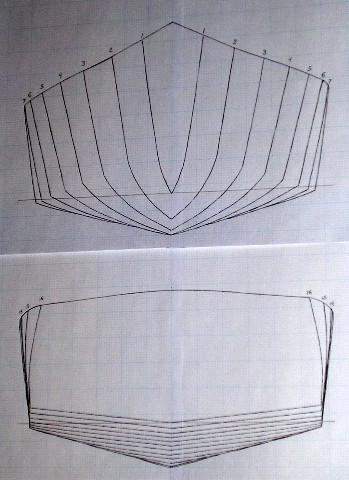
 My final design has a 7" wide plank keel and a 1/3 deadrise slope amidships. This facilitated a low seating position and a low center of gravity. Using a double chine, the hull flared from about 28-30" at the waterline to 42" at the sheer to provide a decent width between oarlocks. Length was limited to 14 1/2', since that was the amount of space between the water heater and furnace in the basement building location. I reduced the upward sweep of the sheer in the ends. I know such a sheer looks pretty, but it is also extra windage.

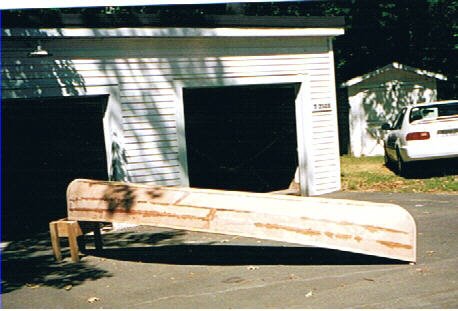
Each hull panel was formed from three projections. Each panel end had a conic projection with another amidships to link the other two. I use just a pocket calculator to do the math and freehand drawings (on engineering graph paper) to visualize the results. Because of the complexity of the hull panels with multiple projections, the hull shape is defined by the boat's skeleton, and the panel shape determined using patterns. Dimensional accuracy is within 1/32". Conic projection tends to produce changing bevels at each frame; thus, I used a plane to set the bevels after the frames were placed on a strongback. Knowing the exact direction of projection and using a straight edge, that is not difficult.

Actual construction was done almost entirely with hand tools in our cramped little basement. When designing, I visualize projections in three types. The parallel projection is the simplest; the direction of projection is contained within a plane formed by two axes in an x,y,z coordinate system and can be defined by a simple slope. It is characterized by identical panel slopes at each station from bow to stern. What I think of as a cylindrical projection cut across all three axes in a coordinate system and can be defined as a ratio, x:y:z. The "cylinder" is not round but instead the shape of the underlying trajectory or other curve. This projection has many of the advantages of the conic projection but is easier to use.

With the conic projection all lines emanate from an apex defined by a set of coordinates (x,y,z). If the apex is positioned too close to the surface being defined, an adjacent area of extreme surface curvature may result. If the apex is positioned too far from the surface being defined, the result has little or no advantage over a cylindrical projection. For me, the conic projection is best used where accentuated local curvature is desired or to link together other projections through converging ruling lines.

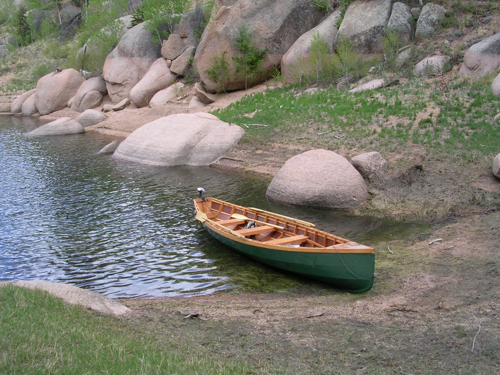
This little green faux guideboat performs great. It is light, dry, buoyant, maneuverable, and fast. I do think it would be faster if it were 1-2' longer. The two seats are removable and when positioned fit snugly around the frames. With one person, the rower's seat and attached footrest is placed in the center of the boat. For two people, the rower's seat is placed on the other side of the oarlocks and the second seat is placed at the other end to maintain balance.

Sunday, May 07, 2006

A real disappointment

We were living in Virginia and had a 60-acre lake just 1 1/2 blocks from our home. I was very busy at my job, but the temptation was there. It had been almost ten years since I built my last boat. Why do we build boats anyway? For me it is the creativity, making reality from just a vision in my mind. In this case my vision was cloudy. I was thinking, row, paddle, motor, maybe sail. A boat designed to do many things will do nothing well, and that's what happened.

The boat was about 3 1/2' by 15', had a double chine and was designed with a parallel projection. This was a very quick boat to build (weeks). No frames. Instead, I used a strongback and set up molds. All the panels were precut; tacked into place; seams epoxied; and a layer of glass laid down. Then popped it off the molds, and the inside was glassed. The weight of all that glass and resin made it heavy to cartop. The big error was that I added a transom, in case I wanted to motor, then added enough rocker to keep the transom out of the water. On a small, round-bottomed boat that takes quite a bit of rocker. Consequently, the boat tracked poorly.

The final insult was that the movers smashed the boat, punching a hole in the bottom, splintering the thwarts and delaminating the plies in the plywood with a smash to the bow. It now serves as a sandbox. And there are no photos I can find.

Panama Skiff

We arrived in Panama just in time that I could buy a few sheets of marine 1/4' plywood before the Panama Canal Company went out of business. No trailers or launch ramps available, shallow coral reefs off all the beaches, but beautiful deserted coves to visit with (by now) an entire family. So I designed a little yellow skiff, 4' (40" waterline beam) by 15 1/2 ', with a daggerboard, rudder and sprit sail. I was able to get Sailrite sail cloth and WEST epoxy through the mail. Again, I calculated the length of the chine, sheer, and sheathing panels and all offsets so that the parts went together smoothly without having to use a strongback. The only drawings I used were just sketches for visualization. I had estimated the hull rocker correctly in design, so the boat performed nicely. We went picnicking, snorkeling, fishing and just exploring. It was light enough that we could cartop the boat on our Toyota wagon to bays along the Atlantic coast.

Kayoe or Canak?

I designed and built my first boat in the mid 70's, when we were living in Nebraska. I was a busy student with limited budget and time. The area has small lakes and shallow rivers and creeks but plenty of wind sweeping in off the plains. So I designed a sort of cross between a canoe and kayak. Double chine, plank keel, low freeboard, partially decked, approx. 16' by 3'. Also, it had to fit out the kitchen window after hauling it up the basement stairs. Using trajectory curve mathematics, I was able to compute the length of both chines, the sheer, and sheathing panel lengths as well as calculating all offsets.

No strongback was needed; all parts fit together as cut. A friend had recently built a Windmill sailboat. He was impressed as I simply put the pieces together. I had used a parallel projection, so all bevels were constant angles which were easy to precut. Consequently, I was able to get tight joints and use resorcinol glue successfully. As an experiment, I built a pair of leeboards, attached a push-pole rudder, and used a closet pole mast and nylon tarp for a sprit sail rig. With this I was able to maneuver up and down the lake but sailing rigs don't get much cruder than this.

Thursday, May 04, 2006

Where does such a wierd interest come from?

Far back in college (1970), I took a sailing course which interested me; all sorts of subtle influencing factors in sailboat behavior. I was studying engineering and needed an idea for a senior research project. So I decided to study sailing hull design. For research I devised a simple hull towing routine: tow hulls with a range of measured forces and record resulting achieved speeds; vary the hull design and evaluate the change in performance.

The next question became, how to exactly describe a hull's shape and how to alter only a single or limited number of variables in the hull so as to independently test the influence of each variable in resulting performance? You can't just say that this hull looks this way and the next hull looks like that. You must be able to describe the hull shape mathematically in exact terms. I found some equations in the Proceedings of the US Naval Institute, but they were far too complicated for my simple project. I found the trajectory curve in physics textbooks, a parabolic equation form, had the right characteristics. Such a curve has the appearance of a boat waterline; it can be integrated to find its length; it can be differentiated to find the slope at any point. It is easy to work with. It describes the motion of an object displaced at some angle from its rest position by an external force which then is brought back to its rest position by gravitational forces. Not exactly the Navier-Stokes equation of general fluid mechanics, but at least it is analogous to the motion of a water molecule displaced by a passing hull form. The research project was successful but very limited in extent due to the complexity of the many variables and the need to build a new model for each design change.

Fast forward a few years: I changed careers forever, leaving engineering for the new profession of dentistry. I didn't dislike engineering intellectually; I just didn't like the environment, being viewed as just a technical nerd, a contract-following migrant laborer. But I didn't want all my engineering knowledge to atrophy. So I picked up my senior research subject and, as a spare-time evening hobby, started playing with the mathematical hull design concepts to create hull forms of interest. Mathematical techniques match very well with the concept of conic projections to produce entire surfaces. Conic projections match very well with the use of plywood hull sheathing which speeds actual construction time. You have to actually build a boat occasionally to prove that your ideas really work (and that you are not completely crazy).

Over the next thirty-plus years I mentally designed a number of hulls for various purposes and I ended up building eleven of them. My family and I have lived in many places. Each hull was designed for a particular set of circumstances and an envisioned purpose. I've learned something from each boat. If I were to revisit any design, I could find improvements to make, but that just makes it interesting. In subsequent entries I hope to post photos of some of the boats I have built and the lessons I learned from them.